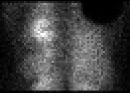

Single posterior projection image (from the tomographic raw data)
View main image(mi) in a separate image viewer
View second image(mi). Daily flood field on the triple-head gamma camera (thought with orientation different from patient image)
View third image(mi). Diagram of gamma camera
Full history/Diagnosis is available below
The gamma camera records data digitally into a two-dimensional array based upon a design by Anger (Anger, 1958). A scintillation gamma camera consists of a lead collimator that collimates the gamma ray photons, a sodium iodide crystal in which the gamma ray photon will cause scintillation, a bank of photomultiplier tubes behind the crystal that converts the weak light from the scintillation event into an electrical current pulse and computer circuitry that calculates the position and strength of the scintillation event. These parts of the camera are described in more detail below:
Collimator: The function of the collimator is to block gamma rays that are not travelling directly toward the camera face. Although not a precise analogy, the collimator serves the same function as the lens of a photographic camera that focusses the image. A gamma ray photon, originating from the injected radiopharmaceutical, will pass through a hole in a parallel-hole collimator if it travels perpendicular to the camera face. The number of photons that pass through the collimator depends on the collimator design. Typically only about 1% of the gamma rays that reach the collimator will pass through the collimator. Collimators are of several designs. The parallel-hole collimator is most common. Pinhole collimators work in the same manner as pinhole photographic cameras. Converging collimators have holes that converge toward the object being imaged and therefore will magnify it. Diverging collimators minify images.
Crystal: The gamma ray photon interacts with the crystal (by the photoelectric effect or compton scatter), releasing one or two high-energy electrons. These electrons pass through the crystal, imparting energy to numerous other electrons, elevating them to the conduction band (i.e., the electrons are knocked loose from their molecular bond orbitals, becoming free to travel through the crystal and, in so doing, leave the valence energy band and enter the higher energy conduction band). The electrons in the conduction band travel through the crystal until they reach an imperfection (the thallium atoms in the thallium-activated sodium iodide crystal) that allows the electrons to pass through the forbidden energy band back to the valence band. In so doing, the energy released is given off as blue and ultraviolet light. On average, for every 30 eV of energy absorbed from the gamma ray, one light photon is given off. Thus, for a 140-keV photon, some 4700 light photons are given off in a scintillation event. Not all of these are detected, however. Roughly 3 light photons are actually detected for every 1 keV of energy absorbed. Photomultiplier tubes: A bank of photomultiplier tubes (PMT s) is located directly behind the sodium iodide crystal and function to convert the weak light signal from a scintillation event into a current flow. When a light photon strikes the photoemissive photocathode face of a PMT, electrons are given off. These electrons travel to a dynode which is at a voltage potential 200 to 400 V higher than the photocathode. When these strike the dynode, several more electrons are given off (on average, about 3 to 6 electrons for each electron that strikes the dynode face). These then travel to another dynode at yet a higher voltage potential, repeating the multiplying effect. Finally, after several dynode stages, a greatly amplified current pulse is detected at the anode. The strength of the current pulse will be proportional to the initial number of light photons detected. The relative current strengths from each PMT of the bank of PMT s is used to calculate the strength and position of the original scintillation event.
PMT malfunctions: If a PMT malfunctions such that no current is detected, then scintillation events occurring under the PMT will not be counted (only weak signals will be detected by neighboring PMT s and the calculated strength of the scintillation event will fall outside the energy window for events to be counted as a primary photon rather than a scatter event). Therefore, a PMT malfunction will manifest as a round defect in a projection image, corresponding to the position of the malfunctioning PMT; due to the nature of the Anger logic and energy windowing, the defect will be larger than the actual PMT. It may be due to a malfunction in the PMT itself or to a loose connection. If due to a loose connection, it may appear as an intermittent problem and may occur at a particular orientation of the camera with respect to gravity. The daily flood field test for uniformity will show a PMT malfunction.
Flood field testing is done daily to assess uniformity. Bar phantoms are obtained weekly to assess linearity and to give a crude check of spatial resolution. The flood field should be checked with and without uniformity and energy correction, since correction may largely mask a defect.
Another problem that will show on a flood field is an improperly adjusted energy window. A slightly larger number of light photons are detected, on average, from scintillation events occurring directly beneath a PMT than from events occurring between PMT s. Therefore, if the energy window is set too high, some scintillation events occurring between PMT s will appear to fall beneath the low end of the energy window and not be counted. The resulting image shows round regions of increased counts corresponding to the locations of the PMT s, with cold areas inbetween. The opposite occurs if the energy window is set too low. (Note that energy correction circuitry may alter this pattern.)
References: Anger, Hal O. Scintillation camera. Rev Sci Instrum. 29: 27-33, 1958. Sorenson and Phelps. Physics in Nuclear Medicine. WB Saunders. 1987.
References and General Discussion of Myocardial Imaging (Anatomic field:Heart and Great Vessels, Category:Other(Artifact))
Return to the Teaching File home page.